Remote desktop software is useful only while the computer is available. If a workstation is powered off, the missing feature is much simpler: a way to press its physical power button without being in the room. AlgoFly's remote PC power project puts that action behind a small ESP8266 web interface.
The video description links a complete Arduino sketch. It contains the embedded browser page, HTTP handlers, WebSocket status updates, reconnect logic, and pin assignments. This companion explains those concrete pieces and the hardware assumptions that need checking before adapting the sketch to a real PC. It does not depend on pretending that a software request confirms the operating system has booted.
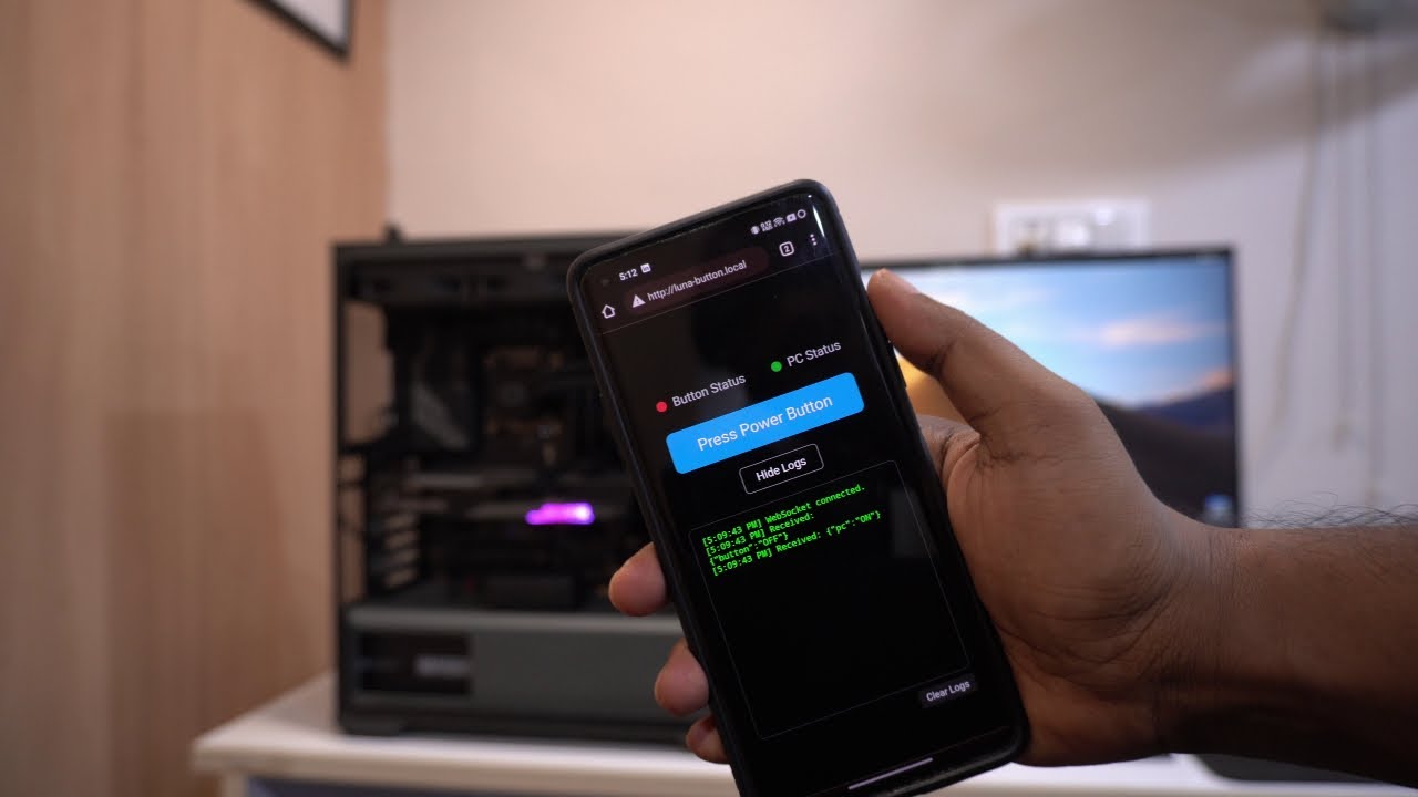
An independent controller next to the motherboard
The controller sits outside the PC's operating system. A relay contact can act like the case's momentary power switch, while a separate input observes the motherboard's power LED signal. The browser talks to the ESP8266, not to an agent running on the workstation.
That separation is the project's main advantage. A crash, an unavailable remote-desktop service, or an ordinary shutdown does not necessarily remove the button controller. It is also why the controller must have a power source that remains available when the PC is off.
The public sketch's comments mention a motherboard 5V supply. An ordinary SATA or peripheral power rail may turn off with the PC, making it unsuitable as the only supply for remotely turning that PC on. Verify actual standby behavior or use a suitable independent low-voltage supply. Do not assume every connector remains live.
The page models a press and a release
The embedded page uses pointer events: pressing the on-screen button sends an “on” request, and releasing, leaving the button, or cancelling the pointer sends an “off” request. That models a physical button more closely than a permanent power toggle.
The firmware also exposes a short-toggle endpoint and a long-toggle endpoint. In the inspected source the configured durations are one second and ten seconds. These values are code defaults, not universal motherboard requirements. A long hold can trigger a forced power-off, which is a different operation from asking an operating system to shut down cleanly.
For a finished interface, separate the normal action from a force-off action and make the latter deliberate. A user should not discover the distinction by holding an unlabeled button for too long.
Button status and PC status are different signals
The firmware keeps two state values: one for the relay/button action and one for the sensed PC signal. The browser displays them as separate indicators. That is a valuable design choice because a successful HTTP response only means a handler ran; it does not prove that the motherboard accepted the press.
On a WebSocket connection, the sketch sends both current states. Later changes are broadcast as JSON records. The page reconnects after a dropped connection, and the firmware checks the power-status input periodically. This gives all connected browser windows a view of the same controller state.
A power LED remains a limited observation. Sleep modes, blink patterns, board wiring, and LED polarity can change what it means. For “ready to work” status, add a separate reachability or application health check rather than renaming a power LED reading to “system healthy.”
Release the button even when a browser disappears
A network can fail between a press request and a release request. The sketch includes an automatic release timer so the controller does not rely only on the browser sending the matching message. That is an important behavior to retain.
One improvement when adapting the design is to express short and long presses as firmware-managed timed actions. The browser requests a bounded pulse, and the device owns its completion. This reduces dependence on pointer event delivery, browser backgrounding, and mobile connection changes.
The published short and long toggle handlers use blocking delay calls. For a more responsive controller, a state machine based on elapsed time can release the relay while continuing to service WebSocket and HTTP traffic. This is an improvement idea, not a claim about the video's implementation.
Validate the actual relay and input circuit
Use the motherboard manual to identify the front-panel power-switch and LED pins. The relay's isolated contact should mimic the intended switch contact; a GPIO should not be connected directly to arbitrary motherboard header pins. The LED sensing path needs appropriate voltage limits and, where appropriate, isolation.
The sketch comments describe an active-low relay, while its output assignments and initial-state comments need checking against the particular relay module. Relay modules vary. Before connecting the PC, test which output level closes the contact, what happens at boot, and whether reset briefly activates it. A label in a code comment is not an electrical measurement.
Work with the PC disconnected while arranging its internal header connections, and keep the project on the low-voltage side. This is a motherboard button accessory, not a project for switching the mains input or opening the power supply.
A local demo is not an authenticated internet service
The sketch hosts HTTP on port 80 and a WebSocket server on port 81, with a local mDNS hostname. Its shown handlers do not implement user authentication. That makes network placement part of the design: keep it on a trusted network and use authenticated private access for remote operation rather than forwarding the raw control ports to the public internet.
Check recovery behavior with the PC off, Wi-Fi temporarily unavailable, the browser closed mid-press, and the controller restarted. Verify both the physical contact and the UI's reported state. These checks reveal whether the device is a dependable remote button instead of a control that only works in the best-case demo.
The project is small, but its lesson is broadly useful: command delivery, physical action, and observed result should be separate concepts. A clear interface can show all three without making remote hardware control complicated.