A satellite image can show thousands of agricultural plots, but a useful agricultural application needs more than a picture. It needs boundaries that can be selected, corrected, measured, and connected to the right location. Our field delineation showcase presents a project using Segment Anything and geospatial tools to move from imagery to field-level information.
The demonstration includes a map interface with administrative area selectors, field outlines, and a field-information panel. This article explains the engineering considerations behind that kind of workflow. It is a project companion and design guide, rather than a released end-to-end reproduction notebook: the video's public description does not provide a full training recipe, source repository, or measured boundary-accuracy benchmark.
The boundary is the beginning of the data model
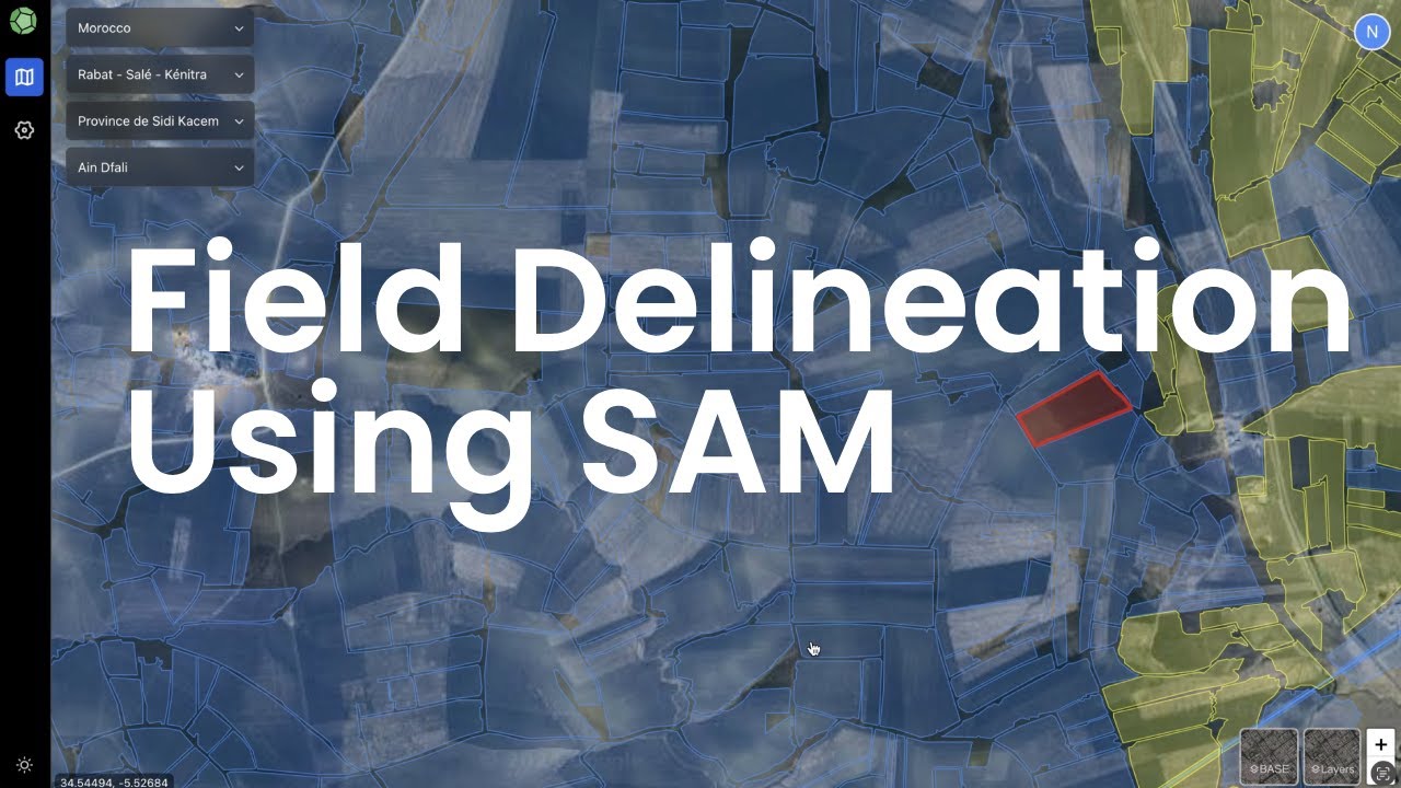
Field delineation identifies the visible extent of an agricultural parcel in imagery. That can support crop monitoring, inventory, or downstream analysis, but a visible vegetation boundary is not automatically a legal ownership boundary. Roads, hedges, irrigation channels, and changes in crop appearance can all influence what is visible.
Keep those meanings separate in the application. A model-generated outline can be a candidate field geometry with a source image and acquisition date. Surveyed or otherwise verified parcel information can be another layer with its own provenance. This prevents an attractive overlay from being interpreted as a level of verification the workflow has not established.
Use promptable segmentation where it helps
Segment Anything provides prompt-based image segmentation. In a field workflow, an operator can indicate a target region and review a proposed mask. The model can help trace visible shapes; the application still needs to determine which proposals correspond to useful agricultural units and how they become map features.
The failure cases deserve attention. A single field may contain several colors or textures because of partial planting or uneven growth. Neighboring fields may look almost identical. A mask can split the first case too aggressively or merge the second. Prompt refinement and manual editing remain useful, especially where irrigation boundaries are faint or imagery is outdated.
Keep the geographic context attached
An ordinary image mask lives in pixel coordinates. A geospatial feature needs a coordinate reference system and a mapping from pixels into geographic space. Before running inference, record the source raster, its coordinate system, its spatial transform, and any preprocessing that changes the pixel grid.
QGIS raster properties provide a place to inspect source information and rendering choices. The colors displayed in a map are not necessarily the raw bands that should be sent to a model. Decide how to construct the image representation explicitly, and preserve that recipe so another scene can be processed in the same way.
For a north-up raster without rotation or shear, a simplified mapping illustrates the idea:
# Conceptual pixel-to-map mapping for a north-up raster.
# Real implementations should use the raster's stored affine transform.
map_x = origin_x + pixel_x * pixel_width
map_y = origin_y + pixel_y * pixel_height
The vertical pixel size is commonly negative in a north-up georeferenced raster. Hand-flipping the result because a browser canvas uses a downward y-axis can therefore create a second flip. Use the stored transformation and verify known locations rather than guessing from how the image looks.
Tile large scenes without losing the joins
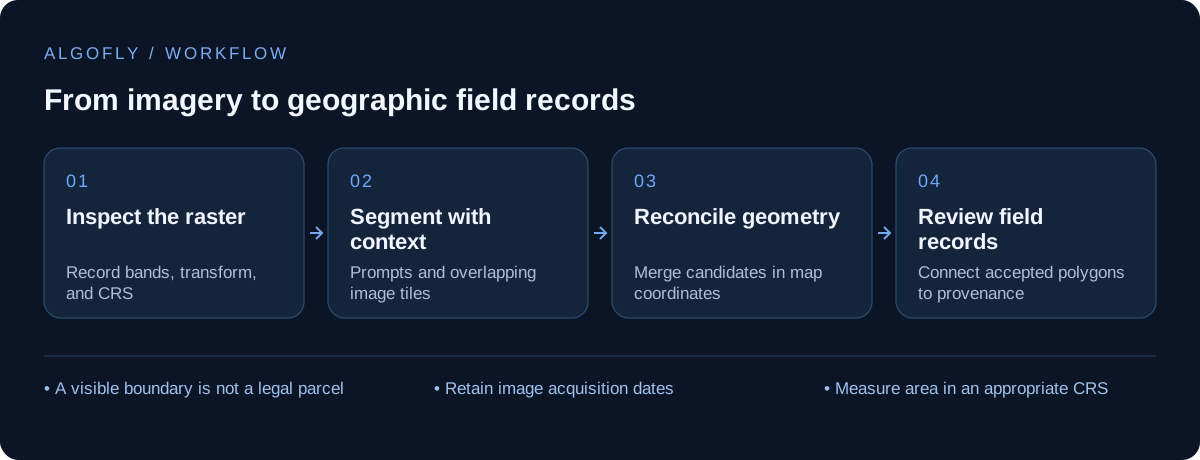
A regional raster may be too large for a single model input. Tiling makes processing manageable, but introduces artificial edges. A field crossing a tile boundary can become two partial masks, or disappear when there is too little surrounding context. Overlap gives the model more context and creates an opportunity to reconcile duplicate predictions.
The merge step should consider location and shape together. Two masks with similar appearance may be different neighboring fields. Two fragments from overlapping tiles may represent the same field. Preserve each tile's offset and transform, move all candidates into one coordinate system, and inspect join behavior before running a whole region.
The right tile size depends on image resolution and typical field size. A tile that works well for small irrigated plots may contain only a fragment of a large field elsewhere. Evaluate several landscapes rather than selecting a size from one appealing screenshot.
Turn masks into editable map features
After segmentation, convert masks into the representation the map workflow needs. Polygonization, simplification, and geometry repair can make boundaries easier to handle, but each can change the result. Record the settings used. Small simplification tolerances can reduce noisy vertices; large ones can remove meaningful bends or narrow strips.
Review geometry relationships as well as individual shapes. Look for unintended overlaps, tiny sliver polygons, self-intersections, and holes caused by image texture. A field mask that looks reasonable on its own can still create an unusable layer when hundreds of candidates are combined.
Area calculations also need a suitable coordinate system. Do not interpret longitude and latitude coordinate differences as square meters. Transform to an appropriate projected system or use a geodesic measurement method, then state which method produced any reported area.
Make the map useful beyond segmentation
The showcase's map selectors and field-information panel illustrate an important product decision: users navigate locations and inspect individual fields, rather than interacting with an anonymous pile of masks. A stable field ID connects the geometry to observations, review status, photographs, and subsequent updates.
Keep model output and accepted geometry distinguishable. A reviewer may redraw a boundary after checking another image or visiting the site. That correction should not disappear when the next processing job completes. Store the model proposal, accepted revision, review event, and source imagery date as separate pieces of information where the workflow needs that history.
Validate boundaries, not just colorful overlays
A useful evaluation set should include small and large fields, different seasons, ambiguous boundaries, and areas with cloud, shadow, or low contrast. Compare predictions against reviewed references, then inspect the cases where neighboring fields merge or individual fields split. Pixel overlap can be useful, but a small gap that changes topology may matter more than its pixel count suggests.
Measure operational effort too. If a person must correct most boundaries, the workflow may still be valuable, but the benefit is assisted editing rather than unattended mapping. Report that distinction clearly. The showcase demonstrates a direction for a geospatial product; it does not establish a universal accuracy or throughput figure for agricultural imagery.
For the related problem of running vision models on large images, our SAHI and sliding-window article explores why resolution and slicing change what a model can see.